4
RF Device Data
Freescale Semiconductor
MRF7S21080HR3 MRF7S21080HSR3
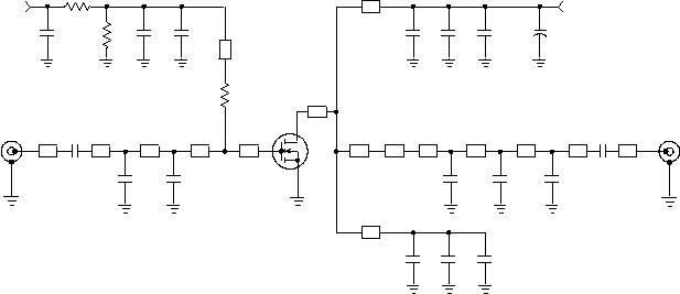
Figure 1. MRF7S21080HR3(HSR3) Test Circuit Schematic
Z10* 0.457″
x 0.083″
Microstrip
Z11* 0.118″
x 0.083″
Microstrip
Z12* 0.206″
x 0.083″
Microstrip
Z13 0.301″
x 0.083″
Microstrip
Z14* 1.220″
x 0.080″
Microstrip
Z15, Z16* 0.720″
x 0.080″
Microstrip
PCB Taconic TLX8--0300, 0.030″,
εr
=2.55
* Variable for tuning
Z1 0.325″
x 0.083″
Microstrip
Z2* 0.921″
x 0.083″
Microstrip
Z3* 0.126″
x 0.083″
Microstrip
Z4* 0.645″
x 0.083″
Microstrip
Z5 0.275″
x 0.669″
Microstrip
Z6 0.114″
x 0.764″
Microstrip
Z7 0.374″
x 0.764″
Microstrip
Z8 0.180″
x 0.524″
Microstrip
Z9* 0.075″
x 0.083″
Microstrip
VBIAS
VSUPPLY
RF
OUTPUT
RF
INPUT
DUT
C4
C3
R1
Z1
Z2
Z3
Z4
C1
Z10
R2
Z14
Z5
Z11
Z12
Z13
C9
Z6
Z15
C10
C13
C16
Z16
C14
C15
+
C12
C11
C5
R3
C2
C17
C8
C7
C6
Z8
Z7
Z9
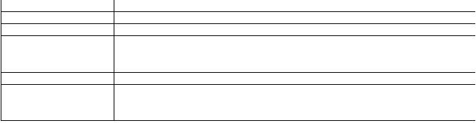
Table 5. MRF7S21080HR3(HSR3) Test Circuit Component Designations and Values
Part
Description
Part Number
Manufacturer
C1, C3, C9, C10, C11
6.8 pF Chip Capacitors
ATC100B6R8BT500XT
ATC
C2
0.5 pF Chip Capacitor
ATC100B0R5BT500XT
ATC
C4
220 nF Chip Capacitor
18125C224KAT1A
AVX
C5, C12, C13, C14, C15
10
μF, 50 V Chip Capacitors
C5750X5R1H106M
TDK
C6
1.5 pF Chip Capacitor
ATC100B1R5BT500XT
ATC
C7, C8, C17
0.2 pF Chip Capacitors
ATC100B0R2BT500XT
ATC
C16
220
μF, 63 V Electrolytic Capacitor, Radial
222213668221
Vishay
R1, R2
2K?, 1/4 W Chip Resistors
CRCW12062001FKEA
Vishay
R3
10
?, 1/4 W Chip Resistor
CRCW120610R0FKEA
Vishay


发布紧急采购,3分钟左右您将得到回复。
相关PDF资料
MRF7S21110HSR5
MOSFET RF N-CH 33W NI-780S
MRF7S21150HSR5
MOSFET RF N-CH 150W NI780S
MRF7S21170HR5
IC MOSFET RF N-CHAN NI-880
MRF7S21210HSR5
MOSFET RF N-CH 63W NI-780S
MRF7S27130HSR5
MOSFET RF N-CH 23W NI-780S
MRF7S35015HSR5
MOSFET RF N-CH 15W NI-400S-240
MRF7S35120HSR5
MOSFET RF N-CH 120W NI-780S
MRF7S38010HSR5
MOSFET RF N-CH 2W 30V NI-400S
相关代理商/技术参数
MRF7S21110HR3
功能描述:射频MOSFET电源晶体管 HV7 33W WCDMA NH780H RoHS:否 制造商:Freescale Semiconductor 配置:Single 晶体管极性: 频率:1800 MHz to 2000 MHz 增益:27 dB 输出功率:100 W 汲极/源极击穿电压: 漏极连续电流: 闸/源击穿电压: 最大工作温度: 封装 / 箱体:NI-780-4 封装:Tray
MRF7S21110HR5
功能描述:射频MOSFET电源晶体管 HV7 33W WCDMA NH780H RoHS:否 制造商:Freescale Semiconductor 配置:Single 晶体管极性: 频率:1800 MHz to 2000 MHz 增益:27 dB 输出功率:100 W 汲极/源极击穿电压: 漏极连续电流: 闸/源击穿电压: 最大工作温度: 封装 / 箱体:NI-780-4 封装:Tray
MRF7S21110HS
制造商:Freescale Semiconductor 功能描述:
MRF7S21110HSR3
功能描述:射频MOSFET电源晶体管 HV7 33W WCDMA NI780HS RoHS:否 制造商:Freescale Semiconductor 配置:Single 晶体管极性: 频率:1800 MHz to 2000 MHz 增益:27 dB 输出功率:100 W 汲极/源极击穿电压: 漏极连续电流: 闸/源击穿电压: 最大工作温度: 封装 / 箱体:NI-780-4 封装:Tray
MRF7S21110HSR5
功能描述:射频MOSFET电源晶体管 HV7 33W WCDMA NI780HS RoHS:否 制造商:Freescale Semiconductor 配置:Single 晶体管极性: 频率:1800 MHz to 2000 MHz 增益:27 dB 输出功率:100 W 汲极/源极击穿电压: 漏极连续电流: 闸/源击穿电压: 最大工作温度: 封装 / 箱体:NI-780-4 封装:Tray
MRF7S21150HR3
功能描述:射频MOSFET电源晶体管 HV7 2.1GHZ 150W NI780HS RoHS:否 制造商:Freescale Semiconductor 配置:Single 晶体管极性: 频率:1800 MHz to 2000 MHz 增益:27 dB 输出功率:100 W 汲极/源极击穿电压: 漏极连续电流: 闸/源击穿电压: 最大工作温度: 封装 / 箱体:NI-780-4 封装:Tray
MRF7S21150HR3_09
制造商:FREESCALE 制造商全称:Freescale Semiconductor, Inc 功能描述:RF Power Field Effect Transistors N-Channel Enhancement-Mode Lateral MOSFETs
MRF7S21150HR5
功能描述:射频MOSFET电源晶体管 HV7 2.1GHZ 150W NI780HS RoHS:否 制造商:Freescale Semiconductor 配置:Single 晶体管极性: 频率:1800 MHz to 2000 MHz 增益:27 dB 输出功率:100 W 汲极/源极击穿电压: 漏极连续电流: 闸/源击穿电压: 最大工作温度: 封装 / 箱体:NI-780-4 封装:Tray
